Posts

RF-8 Conversions

Image
 From Tom's post on Hyperscale: There have been several RF-8 conversions over the years, none particularly good. The first was the War Eagle vac for the ESCI kit. The conversion was in some respects better than the base kit, but not worth messing with, because the ESCI kit is really awful. Two resin conversions were done for the Monogram kit, the one by Maintrack and one by C and H. Of the two, the Maintrack is the more accurate in that it made a real stab at the smaller nose. It is a one piece forward fuselage conversion, but does have a cockpit molded in. C and H just put a Cobra nose cone on a Monogram fuselage which stands out like a sore thumb. Plus, it is also a one piece forward fuselage conversion, but their is one no cockpit! Try doing the intake and cockpit on that! It even buffaloed Phil Brandt. I always hoped Bill Koster would do one, but he didn't. So far there have also been two for the Hasegawa kit: RVHP and, again, C and H. RVHP gives you the who

F8U (F-8) Wing

Image
9 August 2022: Added information about the color of the underside of the wing that was above the fuselage The F8U had two different wings: Original and BLC (Boundary Layer Control). The BLC wing was developed for the French Navy Crusader E(FN) to provide a lower landing speed. It was incorporated in the remanufacture of U.S. Navy F-8Es that were designated F-8J for the same reason but not retrofitted to any earlier F-8s, including rebuilds. When the original wing was raised (to 7° incidence), the leading and trailing edge flaps and ailerons automatically drooped from the cruise neutral position, i.e. leading-edge flaps up. Most of the trailing edge control surfaces were ailerons. A small inboard section next to the fuselage was an actual flap, in that it was either up or down. The trailing edge surfaces drooped 20°. The outboard leading edge flaps drooped 27°; the inboard (center section), 25°. The Unit Horizontal Tail (aka stabilator) moved 5° leading edge up for nose-down pitch

F8U Engines

Image
First some clarification on F-8 engines: from a modeling standpoint there are two types - we'll call them early and late - distinguishable by their afterburner sections.  The early engines—the P4, P12, P16 and P22—all had an afterburner tube that was like a corrugated pipe. Their flame holder was a five-spoke design and the AB petals had a pattern that I call the "waffle iron" pattern.  This engine configuration applies to the F8U-1/F-8A, F8U-1E/F-8B/F-8L, F8U-1P/RF-8A/RF-8G*, and F8U-2/F-8C/F-8K.   The later engines—P20, P20A, and P420—are characterized by an AB petal that I refer to as the "wave pattern", a four-spoke flame holder, and an AB tube comprised of overlapping rings. This engine configuration applies to the F8U-2N/F-8D/F-8H, F8U-2NE/F-8E/F-8J, F-8E(FN)/F-8P ......AND the RF-8G after 1978. A note about the P420 engine.  It came about because the F-8J, which weighed 1500 pounds more than the E and therefore

F-8 Landing Gear

Image
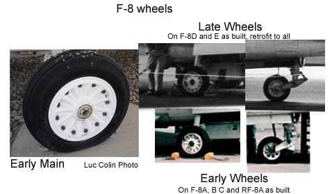
There were changes over time to the landing gear, in part due to the increased gross weight, including the wheel hubs. The original nose landing gear (here, from an E): All rebuild F-8s (F-8H/J/K/L and RF-8G) got new nose gear struts that were about two inches longer than the original and incorporated the cable deflector horns on the wheel forks that had made their first appearance on the A-7 nose strut.  Main Landing Gear: The A-7 design was based (loosely) on the F-8 so there are certain similarities and a definite family resemblance, but there is little commonality between the two, though the main gear is one commonality, at least in part, and in the reverse direction: from A-7 to F-8. In the rebuild program of the late 60's, the H (ex D) and J (ex E) got A-7 main struts. In spite of what is stated in more than a couple sources, no other version got them at that time, though the RF-8G did get them in the late 70's from the retired H and J

F-8 Radome Comparisons

Image
The F-8A through F-8D had a narrow radome (strictly speaking, the A's nose was only a radome at the very tip for a range-finder radar); the F-8E had a wider, round radome. The A/D radome cross-section is on the left; the E's is on the right:  The upper set of pictures is the early radome, the lower is the later one. The F-8A also had a small window on the left side of the nose for a gun camera. The round (wider) radome required a different interface with the forward fuselage (note that the pitot of the E radome has moved from the side of the fuselage as shown above and on the left below to the tip of the radome and the vents aft of the radome are different in number and location): The later round radome was also not symmetrical from top to bottom when viewed from the side:

1/72nd F-8 Kit Review

1. Academy F-8E, F-8E(FN), F-8J. The three listed types have been released, and this is definitely the best 1/72nd F-8, but it is far from perfect, having a lot of warts, most of which it inherited from its illegitimate parent, the Hasegawa 1/48th kit, but some are all its own. Some “genetic” errors include the bogus angled radar screen in the cockpit, the bogus bumps on the upper wing at the wing fold, the flat plank representation of the ACM exhaust fairing on the right fuselage, and the rudder which is not right at the lower forward edge, there should be more of a cut out for the rudder post. A couple errors that are pure Academy are the front windscreen, which has a center section that is about twice as wide as it should be, and the radome cross section, which is egg-shaped , little end up, where it should be an ellipse, long dimension up (It, like all other E kits, is also wrong in profile, being symmetrical when it shouldn‘t be). The latter is not all that no

Summary Differences: Vought F8U/F-8 Crusader

Image
You can't tell the players without a scorecard: